Showing posts with label Arduino Learning with Amit - Experiential Learning. Show all posts
Showing posts with label Arduino Learning with Amit - Experiential Learning. Show all posts
Saturday, September 9, 2023
Wednesday, January 5, 2022
Arduino Series - Part 05
How to interface Ultrasonic sensor with Arduino UNO
Display the results from the HC-SR04 Ultrasonic Sensor on an LCD Display
Hardware Required:
- Arduino Board
- Ultrasonic Sensor HC-SR04
- LCD Display
- 1k ohm resistor
- Breadboard and wires
Ultrasonic Sensor HC-SR04 Connections:

- The HC-SR04 Ultrasonic Module has 4 pins, Ground, VCC, Trig and Echo. The Ground and the VCC pins of the module needs to be connected to the Ground and the 5 volts pins on the Arduino Board respectively and the trig and echo pins to any Digital I/O pin on the Arduino Board.
- The HC-SR04 sensor attach to the Breadboard
- The Sensor VCC connect to the Arduino Board +5V
- The Sensor GND connect to the Arduino Board GND
- The Sensor Trig connect to the Arduino Board Digital I/O 10
- The Sensor Echo connect to the Arduino Board Digital I/O 11
Look the basic tutorial about the HC-SR04 :
LCD Display Connection:
Before wiring the LCD screen to your Arduino or Genuino board we suggest to solder a pin header strip to the 14 (or 16) pin count connector of the LCD screen.
To wire your LCD screen to your board, connect the following pins:
LCD VSS pin to Arduino GND
LCD VDD pin to Arduino 5V
LCD VO pin to 1k ohm resistor
LCD RS pin to digital pin 2
LCD RW pin to Arduino GND
LCD Enable pin to digital pin 3
LCD D4 pin to digital pin 4
LCD D5 pin to digital pin 5
LCD D6 pin to digital pin 6
LCD D7 pin to digital pin 7
The 1k ohm resistor's other legs connect to GND
For the backlight of the display, pin 15 (A+) and 16 (K-) of the LCD connect to +5V and GND
Look the basic tutorial about the LCD Display : https://amit-we.blogspot.com/2021/12/arduino-series-part-04.html
Code:
- The LiquidCrystal library allows you to control LCD displays that are compatible.
- First you have to define the Trig and Echo pins. In this case they are the pins number 9 and 10 on the Arduino Board and they are named trigPin and echoPin. Then you need a Long variable, named “duration” for the travel time that you will get from the sensor and an integer variable for the distance.
- In the setup you have to define the trigPin as an output and the echoPin as an Input and also start the serial communication for showing the results on the serial monitor.
- If the object is 10 cm away from the sensor, and the speed of the sound is 340 m/s or 0.034 cm/µs the sound wave will need to travel about 294 u seconds. But what you will get from the Echo pin will be double that number because the sound wave needs to travel forward and bounce backward. So in order to get the distance in cm we need to multiply the received travel time value from the echo pin by 0.034 and divide it by 2.
#include 'LiquidCrystal.h' //Please replace the single quote characters ('') with the parenthesis character (<>)

LiquidCrystal lcd(1, 2, 4, 5, 6, 7); // Creates an LCD object. Parameters: (rs, enable, d4, d5, d6, d7)

const int trigPin = 9;
const int echoPin = 10;
long duration;
int distanceCm, distanceInch; Saturday, December 11, 2021
Arduino Series - Part 04
Project 2 - Interfacing LCD with Arduino
In Arduino based embedded system design, the Liquid Crystal Display modules play a very important role. Hence it is very important to learn about how to interface LCD with an Arduino of 16×2 in embedded system design. The display units are very important in communication between the human world and the machine world. The display unit work on the same principle, it does not depend on the size of the display it may be big or the small. We are working with the simple displays like 16×1 and 16×2 units. The 16×1 display unit has the 16 characters which present in one line and 16×2 display units have 32 characters which are present in the 2 line. We should know that to display the each character there are 5×10 pixels. Thus to display one character all the 50 pixels should be together. In the display,there is a controller which is HD44780 it is used to control the pixels of characters to display.
What is a Liquid Crystal Display?
The liquid crystal display uses the property of light monitoring of liquid crystal and they do not emit the light directly. The Liquid crystal display is a flat panel display or the electronic visual display. With low information, content the LCD’ s are obtained in the fixed image or the arbitrary image which are displayed or hidden like present words, digits, or 7 segment display. The arbitrary images are made up of large no of small pixels and the element has larger elements.
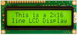
Liquid Crystal Display of 16×2
The 16×2 liquid crystal display contains two horizontal lines and they are used for compressing the space of 16 display characters. In inbuilt, the LCD has two registers which are described below.
- Command Register
- Data Register
Command Register: This register is used to insert a special command in the LCD. The command is a special set of data and it is used to give the internal command to the liquid crystal display like clear screen, move to line 1 character 1, setting the curser and etc.
Data Register: The data registers are used to enter the line in the LCD
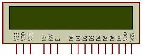
Pin diagram and description of each pin have explained in the following table.
| Pin No | Pin Name | Pin Description |
Pin 1 | GND | This pin is a ground pin and the LCD is connected to the Ground |
Pin 2 | VCC | The VCC pin is used to supply the power to the LCD |
Pin 3 | VEE | This pin is used for adjusting the contrast of the LCD by connecting the variable resistor in between the VCC & Ground. |
Pin 4 | RS | The RS is known as register select and it selects the Command/Data register. To select the command register the RS should be equal to zero. To select the Data register the RS should be equal to one. |
Pin 5 | R/W | This pin is used to select the operations of Read/Write. To perform the write operations the R/W should be equal to zero. To perform the read operations the R/W should be equal to one. |
Pin 6 | EN | This is a enable signal pin if the positive pulses are passing through a pin, then the pin function as a read/write pin. |
Pin 7 | DB0 to DB7 | The pin 7 contains total 8 pins which are used as a Data pin of LCD. |
Pin 15 | LED + | This pin is connected to VCC and it is used for the pin 16 to set up the glow of backlight of LCD. |
Pin 16 | LED – | This pin is connected to Ground and it is used for the pin 15 to set up the glow of backlight of the LCD. |
LCD Interfacing with the Arduino Module
The following circuit diagram shows the liquid crystal display with the Arduino module. From the circuit diagram, we can observe that the RS pin of the LCD is connected to the pin 12 of the Arduino. The LCD of R/W pin is connected to the ground. The pin 11 of the Arduino is connected to the enable signal pin of LCD module. The LCD module & Arduino module are interfaced with the 4-bit mode in this project. Hence there are four input lines which are DB4 to DB7 of the LCD. This process very simple, it requires fewer connection cables and also we can utilize the most potential of the LCD module.
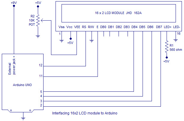
The digital input lines (DB4-DB7) are interfaced with the Arduino pins from 5-2. To adjust the contrast of the display here we are using a 10K potentiometer. The current through the back LED light is from the 560-ohm resistor. The external power jack is provided by the board to the Arduino. Using the PC through the USB port the Arduino can power. Some parts of the circuit can require the +5V power supply it is taken from the 5V source on the Arduino board.
The following schematic diagram shows the LCD module interfacing with the Arduino.
Code:
/*
LiquidCrystal Library - Hello World
Demonstrates the use a 16x2 LCD display. The LiquidCrystal
library works with all LCD displays that are compatible with the
Hitachi HD44780 driver. There are many of them out there, and you
can usually tell them by the 16-pin interface.
This sketch prints "Hello World!" to the LCD
and shows the time.
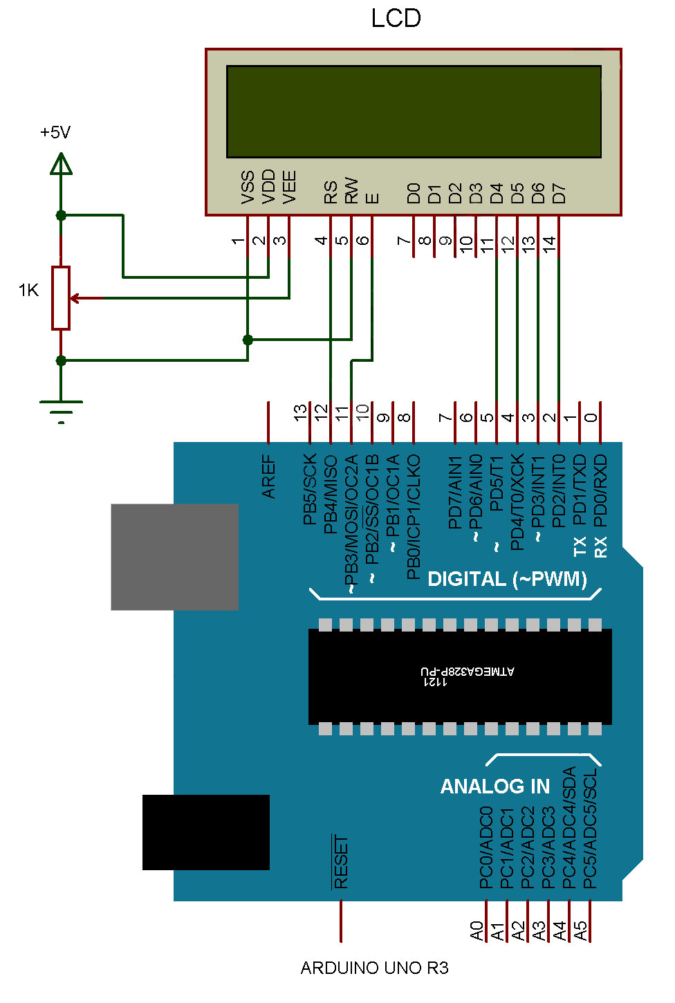
The circuit:
* LCD RS pin to digital pin 12
* LCD Enable pin to digital pin 11
* LCD D4 pin to digital pin 5
* LCD D5 pin to digital pin 4
* LCD D6 pin to digital pin 3
* LCD D7 pin to digital pin 2
* LCD R/W pin to ground
* LCD VSS pin to ground
* LCD VCC pin to 5V
* 10K resistor:
* ends to +5V and ground
* wiper to LCD VO pin (pin 3)
Library originally added 18 Apr 2008
by David A. Mellis
library modified 5 Jul 2009
by Limor Fried (http://www.ladyada.net)
example added 9 Jul 2009
by Tom Igoe
modified 22 Nov 2010
by Tom Igoe
modified 7 Nov 2016
by Arturo Guadalupi
This example code is in the public domain.
http://www.arduino.cc/en/Tutorial/LiquidCrystalHelloWorld
*/
// include the library code:
#include <LiquidCrystal.h>
// initialize the library by associating any needed LCD interface pin
// with the arduino pin number it is connected to
const int rs = 12, en = 11, d4 = 5, d5 = 4, d6 = 3, d7 = 2;
LiquidCrystal lcd(rs, en, d4, d5, d6, d7);
void setup() {
// set up the LCD's number of columns and rows:
lcd.begin(16, 2);
// Print a message to the LCD.
lcd.print("hello, world!");
}
void loop() {
// set the cursor to column 0, line 1
// (note: line 1 is the second row, since counting begins with 0):
lcd.setCursor(0, 1);
// print the number of seconds since reset:
lcd.print(millis() / 1000);
}
Wednesday, November 17, 2021
Arduino Series - Part 03
Project 1 - Digital Input & Output - Push button and LED
In this lesson, every time you press the button, the LED will switch on or off – depending on its current state.
YOU WILL NEED
- LED (1)
- 10,000 Ohm resistor (1)
- 220 Ohm Resistor (1)
- Momentary Push Button (1)
- Jumper Wires (3)
- Goat Cheese
STEP-BY-STEP INSTRUCTIONS
- Connect an Arduino GND pin to one of the long power rails on the breadboard – this will be the ground rail.
- Connect the short leg of the LED to the same ground rail on the breadboard and connect the long leg to a different row on the breadboard.
- Connect the 220-ohm resistor from pin 13 to the same row where the long leg of the LED is attached.
- Place the pushbutton on the breadboard.
- Connect a jumper wire from the 5-volt pin to one side of the pushbutton.
- Connect a jumper wire from pin 2 to the other side of the pushbutton.
- Connect one side of the 10k ohm resistor to the ground rail on the breadboard and the other side to the pushbutton (on the same side that pin 2 connects).
- Plug the Arduino board into your computer with a USB cable.
- Open the Arduino IDE.
- The code for this example is available on the book website.
- Click the Verify button on the top left. It should turn orange and then back to blue.
- Click the Upload button. It will also turn orange and then blue once the sketch has finished uploading to your Arduino board.
- Open the serial monitor window.
- Press the button a couple times and watch how the LED at pin 13 reacts.

THE ARDUINO CODE
DISCUSS THE SKETCH
This sketch is not included in the examples on your Arduino IDE. It is a slightly modified version of the Debounce sketch located in File>Examples>02.Digital>Debounce.
We start this sketch with a handful of variables. Some variables are used to define pins:
Other variables are made to track the state of the button and the state of the LED:
Finally, a couple long data type variables are initialized to keep track of time. The reason these variables are declared as long is because when time is measured in milliseconds the value can become a very big rather swiftly. The long data type can hold a much bigger number than an integer, making it a better-suited option for these variables.
There is a good reason for the above time tracking variables. Remember that the basis of this debounce sketch is to silence input from the pushbutton at pin 2 after the code detects a single state change. When the button is initially pressed the code registers that contact is made. The code takes this reading from pin 2 and then ignores further input until after a couple 10’s of milliseconds later. It is the time tracking variables that enable this to happen.
The setup() for this sketch is rather simple, it only sets pin modes:
The loop() is where things start to get interesting. You may have noticed that the first thing many sketches do inside the loop() is check the state of a pin – that way the code has the most current conditions to work with. This sketch follows the same pattern, we begin by checking the state of pin 2 to see if the button has been pressed or not:
We use the familiar digitalRead() function which takes the pin number you want to check and returns either HIGH or LOW, based on what voltage is read at the pin. In this circuit when the pushbutton is pressed 5 volts is applied to pin 2 (HIGH), otherwise the pin is at ground voltage (LOW).
The next thing we normally do is test the value we just sampled against a condition – in this example, however, we want to check how much time has passed between collecting the current sample and when we received the last sample. If the new sample came in just 1 millisecond after the last sample – we will ignore it. If it came in 2 milliseconds after the last sample, we will ignore it too.
In fact, we only want to accept a sample that was taken at least 50 milliseconds after the last sample. How do we implement this as a condition? We use the microcontrollers internal clock with the function millis():
The above condition takes the current time and subtracts it from the last time a legitimate input was received, it then checks if the span of time is greater than a preset threshold which is named debounceDelay. It basically says, “Has enough time passed for me to even consider a new input?”
This is the gate, the filter, that blocks the noise of a bouncing button. Once we know a reasonable amount of time has passed, we will accept the input and begin to process it.
We use an if-else statement to do more filtering:
We are only interested when the LED goes from LOW to HIGH, this is the rising edge of the input. Pressing the button initiates the rising edge. Releasing the button initiates the falling edge.
The if statement checks these two conditions:
- That the input from pin 2 is HIGH
- That the ledState variable is less than zero (The LED is off – more on this in a moment)
You can see that we have multiple conditions that must be met – we use two ampersands (&&) to join these two conditions together:
This condition asks, “Is the button pressed and is the LED off?” If yes, execute the code inside the if statement. If one of these conditions is not met, the code inside the if statement is skipped. Both conditions must be met for the if statement to execute.
If the condition of the if statement is met, we do three things:
- Turn the LED on
- Update the state of the LED from off to on
- Update the lastDebounceTime variable
Let’s discuss the code block above line-by-line. First, we turn on the LED by using digitalWrite() to apply high voltage to pin 13.
Second, we multiply the ledState variable by a negative one (-1) to change its sign from negative to positive. For our purposes, if the ledState variable is negative it means the LED is off, and if ledState is positive the LED is on. Finally, we update the lastDebounceTime to the current time using the millis() function again.
Now when the button is released the LED will stay on – all we did was toggle the LED from off to on with a button press. What happens when we press the button again? Ideally, the LED turns off.
To turn off the LED we once again refer to the rising edge of the input. We want to know when the button is pressed again – but this time, we want to address the scenario when the button is pressed and the LED is already on. The next part of the code addresses this condition:
The condition of the else-if statement requires buttonState to be HIGH and ledState to be positive (on). Inside this statement, we toggle the LED off by writing digital pin 13 LOW.
TRY ON YOUR OWN
- Try increasing and decreasing the debounceDelay time and observe the effect.
- Add an LED to pin 12 and change the code so that every time you press the button the LEDs toggle between each other (i.e., one is on when the other is off).
Subscribe to:
Comments (Atom)
